OEM Printer Drivers
Imaging Toolkits
Automated Printing
End-User Virtual Printer Drivers
Batch Converters
Printing Tools
Document Viewers
HTML5 Viewers
Forms
Print Automation
Impact Fax
Email Automation
Development Tools
Document Converter Printer Drivers, OEM Printer Drivers for Developers, Auto-print SDK for Automated Printing Solutions, Imaging Toolkits, Barcode Toolkits
Impact Products
BiBatchConverter, Print2Email, Print2RDP, Print2Desktop, BILPDManager, TIFF Viewer, FileFlow, Impact Fax Broadcast
Purchase Information
Support
Knowledge
License Key Request
Newsletters
Company
Buy Now Download
Pricing Feature Chart Online Manual ActiveX Online Manual
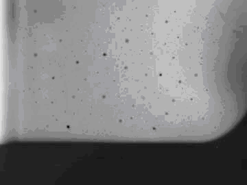
The original image is a 24 bit per pixel X-ray image of porosity welding defects. The small black holes on the image are the defects, and the light grey area of the image is the welding itself. The goal is to detect whether such defects are present or not, and if they are, find these defects (positions, diameter, intensity distribution, etc.)
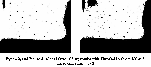
The most important step is to find the exact positions of these defects. First try to segment the image using a global thresholding (HistDIBThreshold in BiFilter.Dll).
As the threshold value increase, the number of defects found will also increase, but also the higher the number of false detections that will occur. Therefore the threshold value must be chosen carefully. Let’s see two examples.
The next step is to try to eliminate all noise from the image and keep only the valid defect positions. Morphological filters are excellent for accomplishing this, but binary morphological filters work only for binary images. In order to use a binary morphological filter, we must first reduce the original 24 bit image’s bit number to 1 bit per pixel. To do this, use one of the dithering functions (like Floyd-Steinberg dithering : DitherFS4 in BiImage.Dll).
Now we must remove the black border on the image in the following way: Remove all the porosity defects in question by applying a binary dilation filter (BinaryDilation in BiFilter.Dll) with a 6 times 6 all one structuring element (the background is black).
The next step is to bit enlarge the black region (the reason for this is because during the dilation above, the area of the black regions were reduced). So let’s erode the image with an 8 times 8, all one structuring function (BinaryErosion in BiFilter.Dll, still the background is black).
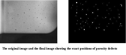
The final step is to combine the result pictures (Figure 2 (or 3), and Figure 5). Let’s create the inverse pictures of both and afterwards subtract (ArithmeticDIB in BiFilter.Dll) Figure 5 from Figure 2.
You are here:
Home > Document Imaging SDK > Finding Defects on an Object - Image Processing Techniques
By using this website, you agree to our use of cookies. We use cookies to provide you with a great experience and to help our website run effectively.